A long time coming...
"I need a counter!", "0~99 counter needed", "How to make seven segment counter"..
Why can no one find a tutorial...
Ah well! Here goes....
First questions you need to ask yourself.... Micro?, language? LCD or LED?..
If you want to use LED seven segment displays, then more questions... Multiplexed or non multiplexed?... Quantity of multiplexed displays?..
LCD display units are relatively easy to hook up to a micro.. Many tutorials on this on the web... So.... Here we are plumping for the old 7-seg types...
If we use the small 7-seg you can easily just hook it up to a micro port with current limiting resistors.... Most LED's are very visible around 8~10mA so if you base the design on 10mA you will need no current drivers... Using a 40 pin Pic, you can drive two/three LED modules directly..
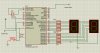
Circuit 1

If you need to use a smaller pic, then you can consider multiplexing... Be warned that multiplexing is time sharing... Each module will get a percentage of display time... Two or three will be okay, but when you are multiplexing 8 modules the time to power the LED will make the LED appear a lot dimmer... You can in these cases "up the current" but the limiting factor will be the capability of the micro pin.. Just because a micro pin can sink 25mA, doesn't mean it will like doing so for ages... Also a micro port will only allow a maximum of 100mA per port... This means 14mA will be the maximum current allowed.. Again, I wouldn't recommend running near to maximum current..
The alternative is by using shift registers with a latched output I have used 74hc595 with good success... Each register can source / sink 25mA per pin... BUT!! Alass the whole device is limited to 70mA... We are back to 10mA which, in fairness, is enough! I put transistor drivers on my LED's, this way I can have the brightness I want..
Anyway, we'll do the multiplexed version afterwards..
Writing the code to dive a seven segment is straight forward. All you really need is a "lookup" table to light the correct LED 's to make sense..
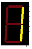
If you want to display the number 1 it looks like this..

Note that to display a 1 then two segments need to be lit.. B and C..
Assuming this display is connected via current limiting resistors to port C of out Pic the output would be binary 00000110 or 6 decimal..
This has been done to death on the web so all the values are here..
In C
In Asm
*Note* when using Common Anode displays just flip the bits with COMF in asm or digit = ~digit; in C..
Moving on.. To place the digit to display just use the decimal representation of the number..
Now each number 0 through 9 has a corresponding LED bitmap and the correct digit will be displayed..
The counter portion is dead easy if you use timer 0.. You can set the port pin 4 on port a to increment the timer with each pulse.. I will not be using any conditioning on the input as each counter input will have differing criteria and that is the fun of design, I'll leave that up to the individual!
Now... Timer 0 is on permanently so you don't have to start it... All that needs to be done is set the input pin and configure the micro to route the input through to the timer!!
The main register we need to worry about is the option register..

The prescaler assignment ( PSA bit 3) selects WDT or Timer 0.. BUT!! using the WDT assignment with the WDT disabled, gives us a 1:1 on timer count and ergo on the pulse input.. Proper counting..
Here goes..
And the C version..
Pressing the button resets the count!!
Now multiplexing.... Virtually the same circuit but only nine pins are used to drive the LED modules... Now!! I don't like multiplexing LED's... They flicker and appear dim.. They don't simulate well... But, with the correct timing, you can get them to display well..
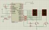
Here's the new circuit..

And here is the updated code
And lastly in C
As you can see there is very little difference to code one from the other..
As I said earlier.. I don't use multiplexing.. I almost always use a shift register.. This way you can keep the segments on as you did in the first example...
I hope these little files find themselves useful to whom ever!!
Now onto serially driven LED modules.. You can daisy chain LED modules forever!!!
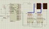
New circuit to cover shift registers..

First note I have used "bussed" wires to connect the LED's to the current limiting resistors.. I have two modules, but many can be linked in with very little change to the code... The display routine is a software "bit banged" routine that used extensively in software serial drivers..
If ULN2003A's are placed between the shift registers and the current limiting resistors.. The large LED modules can be used..
Here is the asm code to drive the two serial LED modules
For those who are fresh to asm coding... Using a pointer is a bit weird... This is the simplest form of indirect addressing... If data is placed in several consecutive memory locations, you can transverse through the data one by one just by increasing a single variable..
The FSR is register that can point to a memory location... The data at that location can be manipulated / accessed though the INDF ( indirection ) register..
Fortunately! C has most of this hidden... Here is the C version..
Again... This is the model that I would use to drive multiple LED modules... The same technique can be used to drive LED matrices as well..
Once again... I hope this helps..
Cheers
"I need a counter!", "0~99 counter needed", "How to make seven segment counter"..
Why can no one find a tutorial...
Ah well! Here goes....
First questions you need to ask yourself.... Micro?, language? LCD or LED?..
If you want to use LED seven segment displays, then more questions... Multiplexed or non multiplexed?... Quantity of multiplexed displays?..
LCD display units are relatively easy to hook up to a micro.. Many tutorials on this on the web... So.... Here we are plumping for the old 7-seg types...
If we use the small 7-seg you can easily just hook it up to a micro port with current limiting resistors.... Most LED's are very visible around 8~10mA so if you base the design on 10mA you will need no current drivers... Using a 40 pin Pic, you can drive two/three LED modules directly..
Circuit 1
If you need to use a smaller pic, then you can consider multiplexing... Be warned that multiplexing is time sharing... Each module will get a percentage of display time... Two or three will be okay, but when you are multiplexing 8 modules the time to power the LED will make the LED appear a lot dimmer... You can in these cases "up the current" but the limiting factor will be the capability of the micro pin.. Just because a micro pin can sink 25mA, doesn't mean it will like doing so for ages... Also a micro port will only allow a maximum of 100mA per port... This means 14mA will be the maximum current allowed.. Again, I wouldn't recommend running near to maximum current..
The alternative is by using shift registers with a latched output I have used 74hc595 with good success... Each register can source / sink 25mA per pin... BUT!! Alass the whole device is limited to 70mA... We are back to 10mA which, in fairness, is enough! I put transistor drivers on my LED's, this way I can have the brightness I want..
Anyway, we'll do the multiplexed version afterwards..
Writing the code to dive a seven segment is straight forward. All you really need is a "lookup" table to light the correct LED 's to make sense..
If you want to display the number 1 it looks like this..
Note that to display a 1 then two segments need to be lit.. B and C..
Assuming this display is connected via current limiting resistors to port C of out Pic the output would be binary 00000110 or 6 decimal..
This has been done to death on the web so all the values are here..
In C
C:
unsigned char DIGITS[] = {0x3F,0x06,0x5B,0x4F,0x66,0x6D,0x7D,0x07,0x7F,0x6F};
Code:
DIGITS
   addwf  PCL  , f
   retlw  0x3F
   retlw   0x06
   retlw   0x5B
   retlw   0x4F
   retlw   0x66
   retlw   0x6D
   retlw   0x7D
   retlw   0x07
   retlw   0x7F
retlw 0x6FMoving on.. To place the digit to display just use the decimal representation of the number..
C:
PORTC = DIGIT[number];
Code:
  movf   number,w
  call    DIGIT
movwf PORTCThe counter portion is dead easy if you use timer 0.. You can set the port pin 4 on port a to increment the timer with each pulse.. I will not be using any conditioning on the input as each counter input will have differing criteria and that is the fun of design, I'll leave that up to the individual!
Now... Timer 0 is on permanently so you don't have to start it... All that needs to be done is set the input pin and configure the micro to route the input through to the timer!!
The main register we need to worry about is the option register..
The prescaler assignment ( PSA bit 3) selects WDT or Timer 0.. BUT!! using the WDT assignment with the WDT disabled, gives us a 1:1 on timer count and ergo on the pulse input.. Proper counting..
Here goes..
Code:
  LIST   p=16F877a     ; tell assembler what chip we are using
   include "P16F877a.inc"     ; include the defaults for that particular chip

   __config 0x3F72       ; sets the configuration bits Watch dog off, HS crystal etc..


digit_unit   equ   0x20
digit_ten   equ   0x21     ; a couple of variables
digit_hun   equ   0x23

   org   0x00
   goto   Init       ; restart vector.. A chance to jump over other vectors.

DIGITS
   addwf  PCL  , f       ; LED bitmap
   retlw  0x3F
   retlw  0x06
   retlw  0x5B
   retlw  0x4F
   retlw  0x66
   retlw  0x6D
   retlw  0x7D
   retlw  0x07
   retlw  0x7F
   retlw  0x6F

Init
   banksel   TRISA       ; Bank 1
   movlw   0xE
   movwf   ADCON1       ; turn off ADC
   movlw   0xff
   movwf   TRISA       ; Port A are all inputs
   movlw   0x1       ; Just port E 0 active
   movwf   TRISE
   movlw   0x00
   movwf   TRISC       ; Tens out
   movwf   TRISD       ; Units out
   movlw   0x28       ; set clock select external, Low to high Prescale 1:1
   movwf   OPTION_REG     ;
   banksel   TMR0
   movlw   0x00
   movwf   TMR0       ; clear timer

   banksel   PORTA       ; Bank 0
   movlw   0x00
   movwf   PORTD       ; dont display
   movwf   PORTC       ; rubbish


loop   btfss   PORTE,0       ; reset count
   call   reset
   call   BCD       ; convert to BCD
   movf   digit_hun,w     ; Hundreds ( if needed )
   btfss   STATUS,Z     ; easy to convert to three digits
   goto   loop       ; this just stops the count at 100
   movf   digit_ten,w     ; Tens
   call   DIGITS
   movwf   PORTC
   movf   digit_unit,w     ; Units
   call   DIGITS
   movwf   PORTD
   goto  loop

reset
   clrf   TMR0       ; reset timer
   return


BCD   movlw   0x00
   movwf   digit_ten     ;
   movwf   digit_hun     ; start count at zero

   movf   TMR0,w       ; get Timer
   movwf   digit_unit     ; put in unit

BCD1
   movlw    0x64       ; bigger than 100
   subwf   digit_unit,w
   btfss   STATUS,C     ; abort if carry set
   goto   BCD2
   movwf   digit_unit
   incf   digit_hun      ; set hundreds
   goto   BCD1       ; loop again
BCD2:
   movlw   0xA       ; bigger than 10
   subwf   digit_unit,w
   btfss   STATUS,C     ; abort if carry set
   return
   movwf   digit_unit     ;
   incf   digit_ten      ; set tens
   goto   BCD1

end
C:
#include<xc.h>         // SFR  definitions
#pragma config FOSC = HS   // Config bits
#pragma config LVP = OFF
#pragma config WDTE = OFF

unsigned char DIGITS[] = {0x3F,0x06,0x5B,0x4F,0x66,0x6D,0x7D,0x07,0x7F,0x6F};   // Led bitmap

void main(void)
   {
   unsigned char dummycnt;     // some variable to use
   TMR0 = 0;           // clear timer
   OPTION_REG = 0x28;       // count on T0CK input 1:1 prescale
   TRISD = TRISC = 0;
   TRISE0 = 1;           // reset button
   ADCON1 = 0xE;         // No ADC

   while(1)
     {
     dummycnt = TMR0;
     if(dummycnt > 99)dummycnt = 99;         // get timer and ensure 0~99
     PORTC = DIGITS[dummycnt/10];   // Tens
     PORTD = DIGITS[dummycnt % 10];   // units
     if(!RE0) TMR0 = 0;         // reset
     }
   }
Pressing the button resets the count!!
Now multiplexing.... Virtually the same circuit but only nine pins are used to drive the LED modules... Now!! I don't like multiplexing LED's... They flicker and appear dim.. They don't simulate well... But, with the correct timing, you can get them to display well..
Here's the new circuit..
And here is the updated code
Code:
  LIST   p=16F877a     ; tell assembler what chip we are using
   include "P16F877a.inc"     ; include the defaults for that particular chip

   __config 0x3F72       ; sets the configuration bits Watch dog off, HS crystal etc..


digit_unit   equ   0x20
digit_ten   equ   0x21     ; a couple of variables
digit_hun   equ   0x23

dly1     equ   0x24
dly2     equ   0x25


   org   0x00
   goto   Init       ; restart vector.. A chance to jump over other vectors.

DIGITS
   addwf  PCL  , f       ; LED bitmap
   retlw  0x3F
   retlw  0x06
   retlw  0x5B
   retlw  0x4F
   retlw  0x66
   retlw  0x6D
   retlw  0x7D
   retlw  0x07
   retlw  0x7F
   retlw  0x6F

Init
   banksel   TRISA       ; Bank 1
   movlw   0xE
   movwf   ADCON1       ; turn off ADC
   movlw   0xff
   movwf   TRISA       ; Port A are all inputs
   movlw   0x1       ; Just port E 0 active
   movwf   TRISE
   movlw   0x00
   movwf   TRISC       ; Tens out
   movwf   TRISD       ; Units out
   movlw   0x28       ; set clock select external, Low to high Prescale 1:1
   movwf   OPTION_REG     ;
   banksel   TMR0
   movlw   0x00
   movwf   TMR0       ; clear timer

   banksel   PORTA       ; Bank 0
   movlw   0x00
   movwf   PORTD       ; dont display
   movwf   PORTC       ; rubbish


loop   btfss   PORTE,0       ; reset count
   call   reset
   call   BCD       ; convert to BCD
   movf   digit_hun,w     ; Hundreds ( if needed )
   btfss   STATUS,Z     ; easy to convert to three digits
   goto   loop       ; this just stops the count at 100
   movf   digit_ten,w     ; Tens
   call   DIGITS
   clrf   PORTC       ; blank display
   movwf   PORTD
   movlw   0x1       ; set for units
   movwf   PORTC
   call    delay       ; view time
   movf   digit_unit,w     ; Units
   call   DIGITS
   clrf   PORTC       ; blank dispay
   movwf   PORTD
   movlw   0x2       ; Tens
   movwf   PORTC
   call    delay       ; time to view..
   goto  loop

reset
   clrf   TMR0       ; reset timer
   return


BCD   movlw   0x00
   movwf   digit_ten     ;
   movwf   digit_hun     ; start count at zero

   movf   TMR0,w       ; get Timer
   movwf   digit_unit     ; put in unit

BCD1
   movlw    0x64       ; bigger than 100
   subwf   digit_unit,w
   btfss   STATUS,C     ; abort if carry set
   goto   BCD2
   movwf   digit_unit
   incf   digit_hun      ; set hundreds
   goto   BCD1       ; loop again
BCD2:
   movlw   0xA       ; bigger than 10
   subwf   digit_unit,w
   btfss   STATUS,C     ; abort if carry set
   return
   movwf   digit_unit     ;
   incf   digit_ten      ; set tens
   goto   BCD1


delay   movlw   0       ; 15ms delay (ish)
   movwf   dly1
   movlw   14
   movwf   dly2

d1   decfsz   dly1
   goto   d1
   decfsz   dly2
   goto   d1
   return

end
And lastly in C
C:
#include<xc.h>         // SFR  definitions
#define _XTAL_FREQ 4000000
#pragma config FOSC = HS   // Config bits
#pragma config LVP = OFF
#pragma config WDTE = OFF

unsigned char DIGITS[] = {0x3F,0x06,0x5B,0x4F,0x66,0x6D,0x7D,0x07,0x7F,0x6F};   // Led bitmap

void main(void)
   {
   unsigned char dummycnt;     // some variable to use
   TMR0 = 0;           // clear timer
   OPTION_REG = 0x28;       // count on T0CK input 1:1 prescale
   TRISD = TRISC = 0;
   TRISE0 = 1;           // reset button
   ADCON1 = 0xE;         // No ADC

   while(1)
     {
     dummycnt = TMR0;
     if(dummycnt > 99)dummycnt = 99;
     RC0 = 0;RC1=0;           // get timer and ensure 0~99
     PORTD = DIGITS[dummycnt/10];   // Tens
     RC0=1;               // set tens
     __delay_ms(15);           // time to view
     RC0 = 0;RC1=0;
     PORTD = DIGITS[dummycnt % 10];   // units
     RC1 = 1;             // set units
     __delay_ms(15);           // time to view
     if(!RE0) TMR0 = 0;         // reset
     }
   }
As you can see there is very little difference to code one from the other..
As I said earlier.. I don't use multiplexing.. I almost always use a shift register.. This way you can keep the segments on as you did in the first example...
I hope these little files find themselves useful to whom ever!!
Now onto serially driven LED modules.. You can daisy chain LED modules forever!!!
New circuit to cover shift registers..
First note I have used "bussed" wires to connect the LED's to the current limiting resistors.. I have two modules, but many can be linked in with very little change to the code... The display routine is a software "bit banged" routine that used extensively in software serial drivers..
If ULN2003A's are placed between the shift registers and the current limiting resistors.. The large LED modules can be used..
Here is the asm code to drive the two serial LED modules
Code:
  LIST   p=16F877a     ; tell assembler what chip we are using
   include "P16F877a.inc"     ; include the defaults for that particular chip

   __config 0x3F72       ; sets the configuration bits Watch dog off, HS crystal etc..


digit_unit   equ   0x20
digit_ten   equ   0x21     ; a couple of variables
digit_hun   equ   0x23

dly1     equ   0x24
dly2     equ   0x25
MSK     equ   0x26
temp     equ   0x27


   org   0x00
   goto   Init       ; restart vector.. A chance to jump over other vectors.


DIGITS
   addwf  PCL  , f     ; LED bitmap
   retlw  0x3F
   retlw  0x06
   retlw  0x5B
   retlw  0x4F
   retlw  0x66
   retlw  0x6D
   retlw  0x7D
   retlw  0x07
   retlw  0x7F
   retlw  0x6F

Init
   banksel   TRISA       ; Bank 1
   movlw   0xE
   movwf   ADCON1       ; turn off ADC
   movlw   0xff
   movwf   TRISA       ; Port A are all inputs
   movlw   0x1       ; Just port E 0 active
   movwf   TRISE
   movlw   0x00
   movwf   TRISC       ; Tens out
   movwf   TRISD       ; Units out
   movlw   0x28       ; set clock select external, Low to high Prescale 1:1
   movwf   OPTION_REG     ;
   banksel   TMR0
   movlw   0x00
   movwf   TMR0       ; clear timer

   banksel   PORTA       ; Bank 0
   movlw   0x00
   movwf   PORTD       ; dont display
   movwf   PORTC       ; rubbish


loop   btfss   PORTE,0       ; reset count
   call   reset
   call   BCD       ; convert to BCD
   call   display       ; serial load LED modules
   goto  loop

reset
   clrf   TMR0       ; reset timer
   return


BCD   movlw   0x00
   movwf   digit_ten     ;
   movwf   digit_hun     ; start count at zero

   movf   TMR0,w       ; get Timer
   movwf   digit_unit     ; put in unit

BCD1
   movlw    0x64       ; bigger than 100
   subwf   digit_unit,w
   btfss   STATUS,C     ; abort if carry set
   goto   BCD2
   movwf   digit_unit
   incf   digit_hun      ; set hundreds
   goto   BCD1       ; loop again
BCD2:
   movlw   0xA       ; bigger than 10
   subwf   digit_unit,w
   btfss   STATUS,C     ; abort if carry set
   return
   movwf   digit_unit     ;
   incf   digit_ten      ; set tens
   goto   BCD1


display
   movlw   0x2       ; two digits
   movwf   dly1
   movlw   0x20       ; We need a pointer
   movwf   FSR       ; Sorry about that!! Read the text!!
outloop
   movlw   0x80
   movwf   MSK       ; start mask at bit 7
   movlw   0x8
   movwf   dly2       ; 8 bits in shift register
   movf   INDF,w       ; point to units
   call   DIGITS       ; gab bitmap
   movwf   temp       ; save it as w is used to death..
inloop
   movf   temp,w       ; get bitmap
   andwf   MSK,w       ; led bit on or off?
   btfss   STATUS,Z
   goto   iset
   bcf   PORTC,4       ; clear data
   goto    unset
iset   bsf   PORTC,4       ; set data
unset   bsf   PORTC,3       ; clock it in MSbit first
   nop
   bcf   PORTC,3
   rrf   MSK,f       ; next bit
   decfsz   dly2       ; loop if needed
   goto   inloop
   incf   FSR,f       ; next digit
   decfsz   dly1       ; all digits??
   goto    outloop
   bsf   PORTC,5       ; clock the store / latch
   nop
   bcf   PORTC,5
   return         ; all done..

delay   movlw   0       ; 15ms delay (ish)
   movwf   dly1
   movlw   14
   movwf   dly2

d1   decfsz   dly1
   goto   d1
   decfsz   dly2
   goto   d1
   return

end
For those who are fresh to asm coding... Using a pointer is a bit weird... This is the simplest form of indirect addressing... If data is placed in several consecutive memory locations, you can transverse through the data one by one just by increasing a single variable..
The FSR is register that can point to a memory location... The data at that location can be manipulated / accessed though the INDF ( indirection ) register..
Fortunately! C has most of this hidden... Here is the C version..
C:
#include<xc.h>         // SFR  definitions
#define _XTAL_FREQ 4000000
#pragma config FOSC = HS   // Config bits
#pragma config LVP = OFF
#pragma config WDTE = OFF

unsigned char DIGITS[] = {0x3F,0x06,0x5B,0x4F,0x66,0x6D,0x7D,0x07,0x7F,0x6F};   // Led bitmap
unsigned char dummycnt;     // some variable to use

void display(void)
   {
   unsigned char x, y;
   unsigned char MSK ;
   unsigned char dig[2];

   dig[1] = dummycnt / 10;
   dig[0] = dummycnt % 10;
   for(x=0;x<2;x++)
     {
     MSK = 0x80;
     for(y=0;y<8;y++)
       {
       RC4 = 0;
       if(MSK & DIGITS[dig[x]]) RC4 = 1;
       RC3 = 1;
       NOP();
       RC3 = 0;
       MSK>>=1;
       }
     }
   RC5 = 1;
   RC5 = 0;
   }

void main(void)
   {

   TMR0 = 0;           // clear timer
   OPTION_REG = 0x28;       // count on T0CK input 1:1 prescale
   TRISD = TRISC = 0;
   TRISE0 = 1;           // reset button
   ADCON1 = 0xE;         // No ADC

   while(1)
     {
     dummycnt = TMR0;
     if(dummycnt > 99)dummycnt = 99;
     display();
     if(!RE0) TMR0 = 0;         // reset
     }
   }
Again... This is the model that I would use to drive multiple LED modules... The same technique can be used to drive LED matrices as well..
Once again... I hope this helps..
Cheers